Solved 153 Design an op ampbased lowpass filter with a Circuit Diagram Key learnings: Active Low Pass Filter Definition: An active low pass filter allows low-frequency signals to pass while blocking higher frequencies, essential for various electronic applications.; Component Significance: The use of an operational amplifier (Op-Amp) is critical for adjusting frequency response and enhancing signal quality.; Filter Design: Active low pass filters can be designed
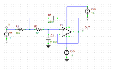
The basic configuration for an active low-pass filter using an operational amplifier is as follows: Place the operational amplifier (op-amp) on a breadboard. Connect a resistor (R) between the input signal source and the non-inverting input ( V in ) of the op-amp.

How to Build an Active Low Pass Filter Circuit with an Op Amp Circuit Diagram
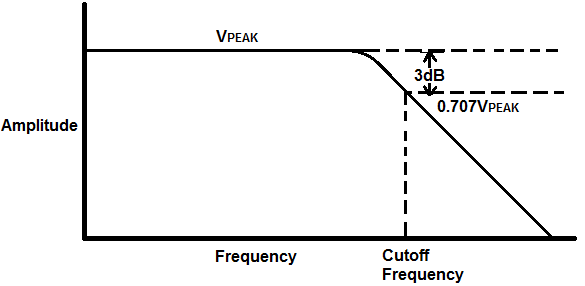
In an active low pass filter, the peak of the passband of the filter can be much larger than the input voltage signal because there is amplification. For passive low pass filters to be built, all that is required are resistors and capacitors. Active low pass filters require either transistors or op amps to provide amplification to the circuit.
View full article: https://www.allaboutcircuits.com/video-tutorials/op-amp-applications-low-pass-and-high-pass-active-filters/In this video we will explore a Step-by-step design of Active low pass filter using Op Amplifier.
Active Low Pass Filter: Design and Applications Circuit Diagram
Second-Order Active High-Pass Filter. If we swap the resistor and capacitor in an RC low-pass filter, we convert the circuit into a CR high-pass filter. We can then cascade two CR high-pass filters to create a second-order CRCR high-pass filter. If we incorporate this passive configuration into the Sallen-Key topology, we have the following: